Rigid Flex PCBs
High-frequency PCBs are essential for enabling advanced technologies like wireless communication devices, radar systems, and high-speed data transmission. But these specialized boards come with their own unique design and manufacturing challenges that require special attention. This article explores some of the most important factors to consider when designing and producing a high-frequency PCB, including signal integrity, electromagnetic compatibility (EMI), and testing and validation.
The primary distinction between high-speed and high-frequency PCBs is the frequency range they are designed to operate at. While high-speed designs prioritize managing signal transitions within the megahertz to gigahertz range, high-frequency PCBs are optimized for consistent operation in the multi-gigahertz and above range. As such, they must deal with a higher level of interference and noise that requires a more pronounced focus on the management of impedance mismatches, signal reflections, and minimizing EMI.
Another key consideration for rigid-flex printed circuit board is the effect of wavelength on signal integrity. At higher frequencies, the skin effect becomes more pronounced, which can lead to currents concentrating near the surface of the conductor and resulting in increased resistance and losses. It is also more likely that the signal will radiate, which can introduce jitter and distortion into the system. Achieving optimal performance requires implementing measures to mitigate these issues, including designing for controlled impedance, minimizing via stubs, and using materials with low dielectric losses.
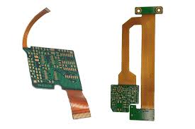
Rigid Flex PCBs and High-Frequency Signals
Rigid-flex circuit boards are uniquely suited for handling high-frequency signals due to their flexibility and bending capabilities. They can be used in places where multiple rigid boards, connectors, and wiring harnesses would be needed to achieve the same results. They can also be fabricated with thinner, more tightly controlled impedance trace widths to support lower core and copper thicknesses, which increase mechanical bend reliability and reduce power loss.
High-speed flex and rigid-flex PCBs can be designed with differential signaling, which is beneficial for high-data-rate applications. This approach uses a pair of conductive paths to transmit information by comparing two separate signals to determine whether they are in the same or opposite logic state. This can provide higher noise cancellation and data accuracy than single-ended connections.
When working with high-frequency PCBs, it’s critical to familiarize yourself with regional and industry standards that govern EMC/EMI compliance. This will ensure that your board functions correctly in its intended application and meets all applicable regulatory requirements to avoid costly modifications after production. Rigorous testing and validation are essential for ensuring that your board meets its performance specifications, which can uncover signal integrity, impedance mismatch, and EMI problems that may not be obvious during the design process. Testing can also help you identify and resolve any issues before seeking formal EMC/EMI certification, reducing the risk of expensive design changes after production.